
Before we start discussing protocols, routing, switching, and network attacks, we must first understand the conceptual framework used to describe how network communication works.
The OSI Model is one of the most important concepts in networking.
It provides a structured way to think about communication between systems by dividing networking responsibilities into separate layers.
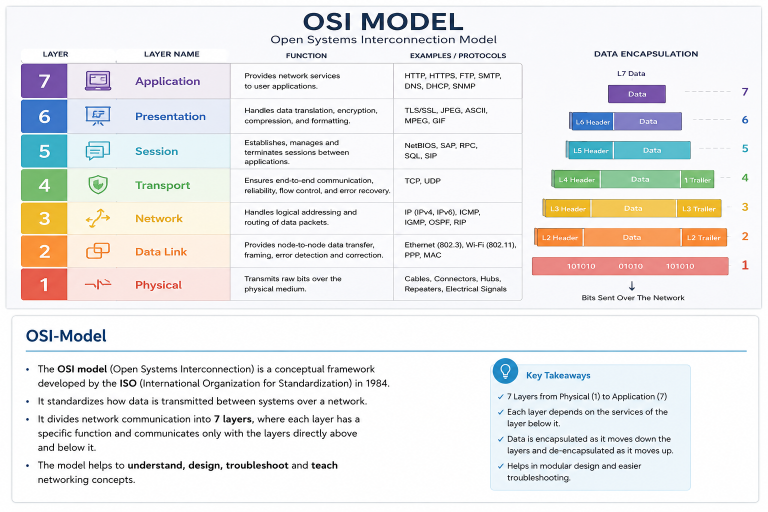
Why The OSI Model Exists
Imagine trying to troubleshoot a network problem without any structure.
A user says:
"The website doesn't load."
What does that mean?
- Cable unplugged?
- Switch failure?
- Wrong IP?
- DNS failure?
- Firewall blocking traffic?
- Web server offline?
Without a framework, troubleshooting becomes chaos.
The OSI Model solves this by dividing networking into layers.
Each layer is responsible for a specific part of communication.
Core Principle
Each layer provides services to the layer above it.
Layer 7
    ↓
Uses Layer 6

Layer 6
    ↓
Uses Layer 5

Layer 5
    ↓
Uses Layer 4

...
No layer needs to know how the lower layers actually work.
It only uses the services they provide.
Layer 1 — Physical
The Physical Layer is responsible for transmitting raw bits.
It deals with:
- Electrical signals
- Light signals
- Radio waves
- Cables
- Connectors
Examples:
Ethernet Cable
Fiber Optic Cable
Wi-Fi Radio Signal
The Physical Layer does not understand:
IP Addresses
Ports
Protocols
Packets
It only moves bits.
Unit of data:
01100111 01101111 00100000 01100010 01100001 01100011 01101011 00100000 01110100 01101111 00100000 01100011 01101100 01100001 01110011 01110011 00100000 01101100 01101111 01101100
Layer 2 — Data Link
The Data Link Layer is responsible for communication between devices on the same local network.
Its primary job is framing and MAC addressing.
Example:
PC → Switch
Layer 2 identifies devices using:
MAC Addresses
Example:
00:11:22:33:44:55
Common technologies:
Ethernet
Wi-Fi
Devices operating primarily at Layer 2:
Switches
Bridges
Unit of data:
Frame
Layer 3 — Network
The Network Layer is responsible for routing traffic between networks.
This is where IP addresses live.
Example IPv4:
192.168.1.10
or IPv6:
2001:db8::1
Layer 3 determines:
How do I reach another network?
Devices:
Routers
Layer 3 Switches
Protocols:
IPv4
IPv6
ICMP
Unit of data:
Packet
Layer 4 — Transport
The Transport Layer is responsible for end-to-end communication between applications.
Its responsibilities include:
- Reliability
- Flow Control
- Error Recovery
- Segmentation
The two most important protocols are:
TCP
UDP
TCP:
Reliable
Connection-oriented
Acknowledgements
Retransmissions
Ensures the traffic is received
Example:
Web Browsing → TCP
UDP:
Fast
Connectionless
No reliability guarantees
Sends traffic without ensuring it is received
Examples:
Video Streaming → UDP
VoIP → UDP
Unit of data:
Segment
Layer 5 — Session
The Session Layer manages communication sessions between systems.
Responsibilities:
Session Establishment
Session Maintenance
Session Termination
Example:
User logs into a remote application
A session is created and maintained.
Modern networking often merges Session functionality into higher layers.
Because of this, Layer 5 is rarely discussed independently in real-world environments.
Layer 6 — Presentation
The Presentation Layer is responsible for data representation.
It answers:
How should data be formatted?
Responsibilities:
Encryption
Compression
Encoding
Translation
Examples:
TLS/SSL
ASCII
UTF-8
JPEG
PNG
Example:
Plain Text
      ↓
TLS Encryption
      ↓
Encrypted Data
Layer 7 — Application
The Application Layer is the closest layer to the user.
This is where applications interact with network services.
Examples:
HTTP
HTTPS
FTP
DNS
SMTP
SSH
Applications operating here:
Chrome
Firefox
Outlook
curl
wget
Important:
The Application Layer is not the application itself.
It is the networking functionality used by applications.
Encapsulation
One of the most important networking concepts is encapsulation.
As data moves down the OSI stack, each layer adds information.
Example:
Application Data
Layer 4 adds:
TCP Header
Layer 3 adds:
IP Header
Layer 2 adds:
Ethernet Header
Result:
[Ethernet]
    [IP]
        [TCP]
            [Data]
This process is called:
Encapsulation
The receiving host performs:
De-encapsulation
removing headers layer by layer.
Real Example — Loading A Website
You open:
https://example.com
Application Layer:
HTTP Request
Presentation Layer:
TLS Encryption
Transport Layer:
TCP Segment
Network Layer:
IP Packet
Data Link Layer:
Ethernet Frame
Physical Layer:
Electrical Signals
The server receives the traffic and reverses the process.
What Security Professionals Care About
Different attacks occur at different layers.
Layer 2:
ARP Spoofing
MAC Flooding
Layer 3:
IP Spoofing
Routing Attacks
ICMP Abuse
Layer 4:
Port Scanning
TCP Hijacking
SYN Flooding
Layer 7:
SQL Injection
XSS
Authentication Bypass
API Abuse
Understanding the OSI Model helps us quickly determine:
Where a problem exists.
Where an attack occurs.
Where a defense should be implemented.
Operator Notes
The OSI Model is not a perfect representation of modern networking.
Many modern protocols blur the boundaries between layers.
However, it remains one of the most useful conceptual frameworks for:
- Understanding network communication
- Troubleshooting connectivity problems
- Learning protocols
- Understanding attacks and defenses
For offensive operators and defenders alike, the OSI Model provides a mental map that explains where data exists, how it moves, and where it can be observed, manipulated, or protected.